The design of PV systems can be fairly simple as well as extremely complex. No matter how difficult or easy, it is important to document the design process. Doing so will help flush out issues early in the process, provide references for installation crews, and will of course, provide a means for permitting and interconnecting the PV system. There are three basic diagrams that are used to represent the electrical design of a PV system. These are block diagram, single-line diagram and three-line diagram. Below are descriptions and examples of each.
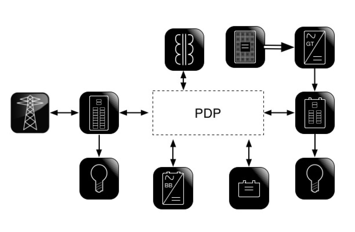
A block diagram is a diagram of the PV system that shows relationships between all of the major components comprising the PV system. Block diagrams present an organized visual representation of the system in question. They are used to help conceptualize relationships of major components at a high level. Details are usually limited to major component specifications and quantities. For example, Figure 1 below presents a block diagram of a residential AC-coupled PV system. Notice that the block diagram specifies quantities of major components and basic electrical characteristics of each major component. Simply put, a block diagram provides a simple conceptual overview to help aid the design process and help specify major equipment. Once components and quantities are defined, the design process can move onto development of a single line diagram.

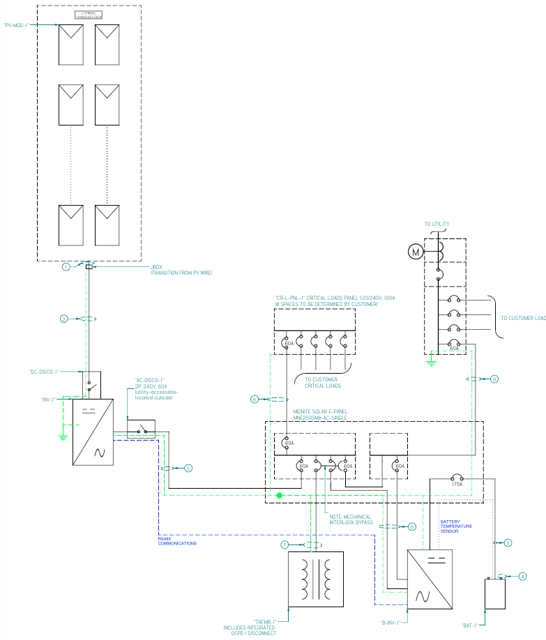
A single-line diagram is similar to a block diagram in that it presents the relationships between all major components. However, the single line dives deeper into the design by specifying electrical characteristics of each component in the system as well as all circuit segments. Single line diagrams are accompanied by a conductor/conduit schedule, equipment schedule and a table of all OCPDs and corresponding ratings. Figure 2 below presents a single line diagram of a residential AC-coupled PV system. Notice that it much more detailed when compared to a block diagram. Note: conductor/conduit, equipment and OCPD tables are not presented in the figure below.
Single line diagrams are utilized to document the engineering process of specifying equipment, conductors and OCPD. They provide a means to ensure that all system components and circuits are compatible and that the system is designed according to local codes and standards. A single line is usually sufficient for permitting and interconnection needs, However, depending on AHJ requirements and system complexity, a three line diagram may be needed / required.

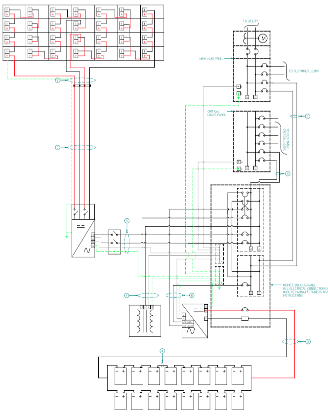
A three line diagram is a complete wiring diagram of the PV system showing all conductors at each circuit segment and connections of these conductors to electrical equipment. Some extremely detailed three lines present connections to electrical equipment at the terminal level. Figure 3 below presents a three-line diagram of the same residential AC-coupled PV system as the previous two figures. Notice that each conductor is presented. Note: conductor/conduit, equipment and OCPD tables are not presented in the figure below.

The three documents described above; block diagram, single-line diagram and three-line diagram, provide a means for documenting the design process of a PV system. The process starts at the conceptual stage where major equipment is chosen to meet a certain need. To help in the decision making a block diagram can be developed to help organize how the major components relate to each other. When this phase is complete, the next step is to develop a single-line diagram. This document is developed to specify all system components, their electrical specifications and to define circuit requirements for interconnecting all components. The single line is a record of the system design that follows AHJ codes and standards. Finally, a three-line diagram, if needed/required, presents a detailed wiring diagram of the system, showing all conductors of all circuits and connections between all system components. Documenting the design is a must, even if not required. Going through the process of developing even a block diagram will prove useful in working out issues that would otherwise surface during the installation. It is much easier to erase (or redraw) than rewiring/reworking/reordering.